↧
Bitx Ver 3 Built By Paul Cotton
↧
Bitx Version 3 B PCB's Components Layout
After much hard work for a few months the PCB's for the Bitx Version 3 B are ready. Very soon we will start accepting orders for the Bitx Ver 3 B Kits. The case is also ready we will be sharing the pictures very soon.
Highlights for the Bitx Version 3 B
1. Basic Operation 20mt band kit
2. VFO Varactor Tuned
3. Inbuilt Mic Pre Amplifier
4. Audio Mute on TX
5. No Hissing of RX on receive,as a filter is used in audio to suppress the hissing sound
6. Full connectivity of FLL counter and control for VFO drift
7. Connection points for Freq Counter FLL Type
8. AGC Module Extra Mounted on VU Meter.
This design is an upgrade from Bitx Version 3. The original Bitx design belongs to the author OM Farhan from India.
This new design was suggested by a few Italian Hams, we took the Basic design and added further mods.
The design made by Italian Hams did not have the Connections and buffer in VFO for the FLL Freq counter,or the anit hissing filter in the audio amplifier. nor the AGC module, which is mounted on back of a VU Meter. So we had to do a lot of testing after making several boards and testing them we finally made these boards.
The good news is that the Manual is being made by OM Leaonard , who has a great experience with the Bitx 3 and Bitx 20a
The Manual may take some time. The basic manual is same only with certain changes in the VFO, Audio and TX Pre amp. So we will presently provide with some head on start notes.
BITX VERSION 3 B
AGC MODULE
LINEAR AMP
Highlights for the Bitx Version 3 B
1. Basic Operation 20mt band kit
2. VFO Varactor Tuned
3. Inbuilt Mic Pre Amplifier
4. Audio Mute on TX
5. No Hissing of RX on receive,as a filter is used in audio to suppress the hissing sound
6. Full connectivity of FLL counter and control for VFO drift
7. Connection points for Freq Counter FLL Type
8. AGC Module Extra Mounted on VU Meter.
This design is an upgrade from Bitx Version 3. The original Bitx design belongs to the author OM Farhan from India.
This new design was suggested by a few Italian Hams, we took the Basic design and added further mods.
The design made by Italian Hams did not have the Connections and buffer in VFO for the FLL Freq counter,or the anit hissing filter in the audio amplifier. nor the AGC module, which is mounted on back of a VU Meter. So we had to do a lot of testing after making several boards and testing them we finally made these boards.
The good news is that the Manual is being made by OM Leaonard , who has a great experience with the Bitx 3 and Bitx 20a
The Manual may take some time. The basic manual is same only with certain changes in the VFO, Audio and TX Pre amp. So we will presently provide with some head on start notes.
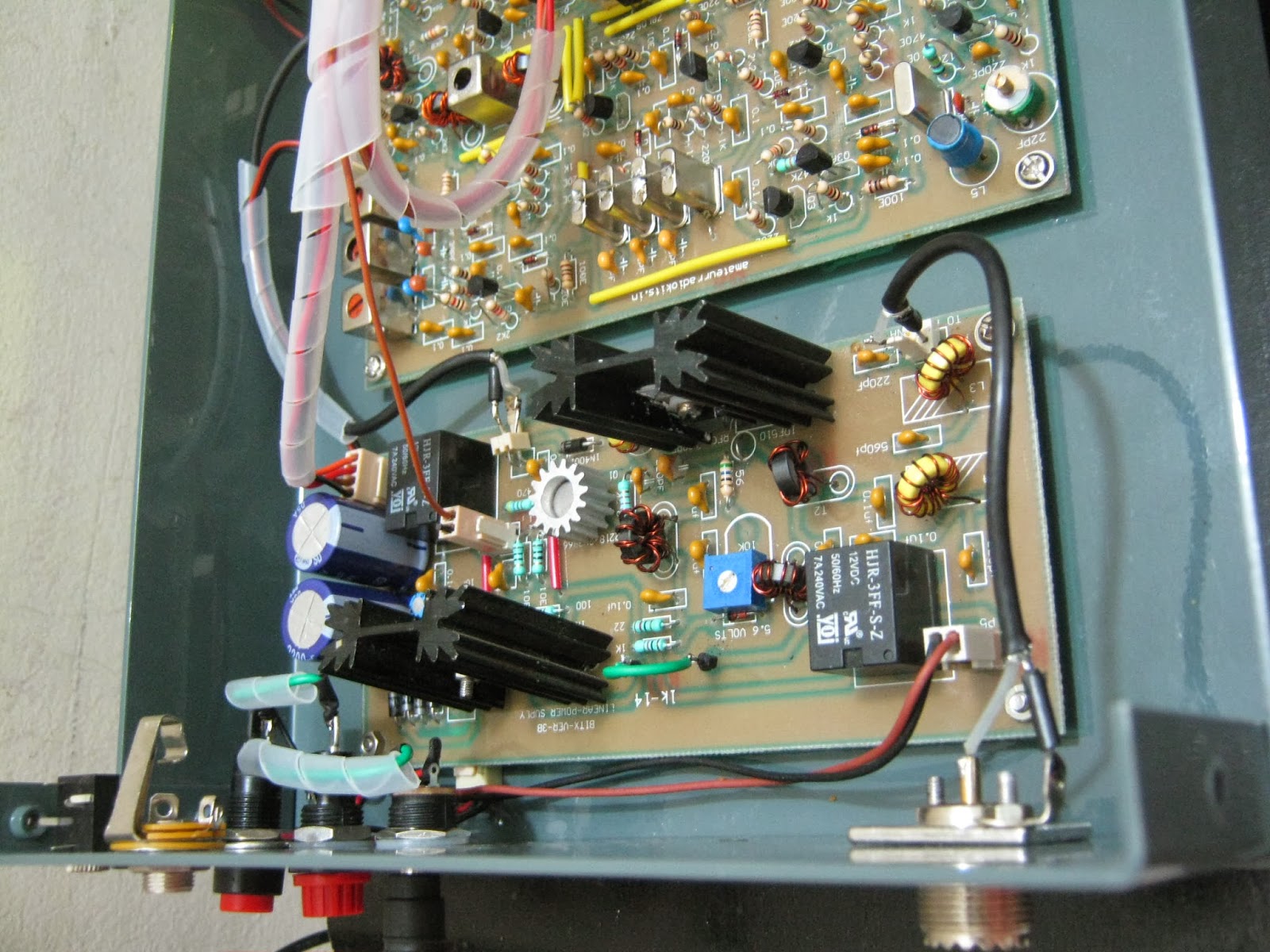
PICTURES OF BITX VERSION 3B PCB
BITX VERSION 3 B
AGC MODULE
AGC MODULE
LINEAR AMP
↧
↧
Pictures Bitx Version 3 B
At last we have the Bitx 3 B just about ready to be offered as a Kit.
Its a great moment to share some pictures of the Bitx version 3 B .
The pictures are of the Bitx 3B case, PCB set.. Exiter-PA-AGC Module.
A semi finished Bitx 3 B board is also shown.
The process of packing of Kits is on and very soon the sale will start.
I will also upload a video of the working prototype soon, in fact i had already tested 2 boards
earlier .
The complete manual of Bitx 3 B is not ready,but we have details for all the changes and the
schematics too, which will be uploaded on our website http://amateurradiokits.in very soon.
Best of 73s.
BITX VERSION 3 B PICTURES
↧
Bitx Version 3 B Completed Pictures of Printed Circuit Boards
During past few days i was able to complete a Bitx Ver 3 B set Exiter and PA Board .Some pictures are being published here. The RX is working okay and the FLL seems to be correcting minor drift.
I have still to place all the modules in the case for final assembly.
PICTURES OF BITX VER 3 B
BITX VERSION 3B EXITER
BITX VERSION 3B PA
BITX VERSION 3B SET
↧
Pictures of Working Bitx Ver 3B
It is a pleasure to present pictures for a complete working Bitx B .
The Bitx Ver 3B has not been put on sale as yet, although i have sold 3 sets on request.
Two radio amateurs are building the set but are facing some problem in their sets audio.
I will also upload a video very soon giving a live demo of the working Bitx Ver3B in receive and a modulation test on a dummy load and swr bridge and modulation monitored on a commercial receiver.
The Bitx Ver 3 B has some changes that were made to make it much more convenient for operational use.
The changes were.
1. Stable VFO drift with in 50 to 100 hertz in time span of few hours
2. Mic Preamp so that there no need to shout in the mic.. hi hi
3. FLL Freq counter connectivity with a buffer added in the vfo
4. Aluminum case
5. Mic PTT and Speaker
PICTURES OF BITX VERSION 3 B
↧
↧
Bitx Version 3 B SSB TCVR . Demo of RX
Here is a video i took last night for the Bitx Version 3 B in receive mode.
I have taken some more videos which i will post soon.
The receiver is quite sensitive and the VFO is quite stable. Since it is a var actor VFO i am quite satisfied with its stability . The maximum drift i observed in 12 to 15 hours not more then 50 to max 100 hertz in a period of 12 to 15 hours time.
More news of Bitx Version 3 coming soon.
↧
Bitx Ver 3 B RX demo
↧
Article 17
↧
New Ham Radio TCVR Minima
Om Farhan from India has come up with another Ham Radio project. The new project is named Minima, which means a project with minimum components.
Minima is a complete ssb/cw tcvr with Arduino in it and an Si570.
Farhan's home page on minima is found here http://www.phonestack.com/farhan/minima.html
To carry on with our services we have decided to help amateurs buy our various products based on Minima.
We are starting by selling the PCB developed by our forum member as very low cost, as to promote the building of Minima. Very soon we will provide a complete kit with case for Minima .
Please look out the availability of the PCB set for Minima, which will be available very soon on our new blog meant for Minima. http://cqminima.blogspot.com
We have also set up a new blog for bitx version 3 B, which will be updated with all info on Bitx3B
http://bitxversion3b.blogspot.in/
Best of 73s
Sunil VU3SUA
↧
↧
Audio Mute Circuit For Bitx
Bitx had a problem of noise being generated on pressing the PTT button. The usual way of muting the PIN 3 of LM386 did work to solve the problem much, although to some extend, while working with Bitx3b i had discussion regarding this problem with Om Blake Bartosh from USA who was also building the Bitx Version3b and who has also put in a great effort in bringing out the new Bitx3b construction manual.
The idea was to make a project to mute the audio of LM386 completely.
Presented below is a schematic of the audio mute circuit designed and tested by OM Blake Bartosh.
I myself build it and its working perfectly with my bitx3b. This circuit can be used for any tcvr.
The complete assembled kit will be available very soon.
SCHEMATIC OF BITX AUDIO MUTE CIRCUIT
VIDEO OF BITX AUDIO MUTE CIRCUIT
The idea was to make a project to mute the audio of LM386 completely.
Presented below is a schematic of the audio mute circuit designed and tested by OM Blake Bartosh.
I myself build it and its working perfectly with my bitx3b. This circuit can be used for any tcvr.
The complete assembled kit will be available very soon.
SCHEMATIC OF BITX AUDIO MUTE CIRCUIT
![]() | ||
↧
Bitx3B VFO
The Bitx3B has a Varactor tuned VFO using MV209 and the stability is controlled with the Ik3OIL FLL Freq counter which has an inbuilt software to correct the drift in the VFO.
Building a stable vfo is an art and if not built correctly it would not perform optimum.
Picture and Video below outlines some important factors that could enhance the performance.
↧
Explanation of how the delay circuit works.
Om Blake Bartosh has shared with us the explanation as to how the delay circuit works as you may be eager to try it out on your Bitx. The Audio Mute circuit operates in the following way. The 555 timer is connected to the PTT switch and generates a 100 msec pulse when PTT is engaged and another 100 msec pulse when PTT is released. The 555 timer is configured as a debounce circuit, so contact bounce of the PTT switch does not initiate any new pulses. The output of the 555 timer and the PTT switch signal are combined in logic to form two signals, a mute command and a transmit command. The mute command turns on Q16 of the Exciter board which shorts the audio signal to ground, and no sound is heard from the speaker. The mute command occurs immediately upon engaging PTT, but the transmit command is delayed by 100 msec. This delay ensures audio transients due to switching from receive to transmit mode do not cause a "pop" in the speaker, but is not so long as to be noticeable to the operator. The transmit command energizes the relay coil of K2 of the PA board via a 2N3904 transistor and the rig switches to transmit mode. Upon releasing PTT the transmit command is immediately turned off, K2's relay coil is de-energized and the rig reverts to receive mode. 100 msec later the mute command is turned off and the speaker is activated again. The Audio Mute circuit is powered by 12V+, and a voltage regulator reduces the 12V+ voltage to +5VDC required by the 555 timer and the 74LS00 quad NAND gate IC.
↧
Bitx3B VFO
The FLL frequency counter used for Bitx3B may sometimes not read the frequency from the Bitx3b VFO stage, the reason being the VFO buffer has a low output kept for the stability of the VFO. It is observed that in some cases the Freq counter does not read the freq and some times it does, some transistors may have a higher gain and some lower as the brand is not same for all the kits we supply the 2n3904 transistor. Due to the different gain of transistor the issue of FLL not reading the freq arises.
The solution is simple without disturbing the VFO capacitors value's we just need to change C13 in the FLL Freq counter from 22PF to 47 PF. I tied this and it works fine. Here is a picture of FLl Freq counter with FLL C13 that has to be changed to 47PF
The second issue of VFO Freq Stability. T50-6 was tried on the VFO of Bitx3B with around 50 turns. Kindly adjust turns to reach 4.MHZ reading on the VFO, you may have to wind turns as per need, if you connect the FLL freq counter you could wind the turns with out much trouble.
I must admit that T50-6 is much much better with no drift at all. in the VFO. I was able to have a qso with VU2YK on this Sunday for more than 15 minutes with a very stable VFO with zero drift . Also I took a video of Bitx3B showing the freq stability. This Video taken with the antenna not connected, just to check the VFO on power on.
The VFO works okay also with the T37-6 with very less drift but was found better with T50-6. Next experiment is to try 2 nos of T37-6 stacked together. I shall publish the result soon.
↧
↧
Bitx 3B PCB second batch
The second batch of Bitx 3b PCB now has the following changes from the first batch of pcb's made.
1. Q16 is not on the main exciter PCB now, instead we have a additional PCB of audio mute
delay circuit. Please observe connections for integrating the connections from the schematics.
2. Two components have been added in the mic pre amp. 100UH and .001 at the mic pre amp circuit.
for better filteration of audio coming from the microphone.
3. Two pin connector's point has been added at
a. VFO for DDS optional use.
b. Audio to agc circuit
c. LM386 Audio Mute point taken to the Audio Mute PCB
Some Important Points:
1. We recommend the VFO coil to be wound with 2 nos of T37-6 stacked with about 40 turns plus or minus a few turns, for more stable VFO. The coil has to be glued with quick fix for better stability.
The second recommended VFO coil is on T50-2. Single coil. Both work as very stable VFO's
For Drift:
The VFO has two trimmers. The first towards the VFO coil is for fine tuning your VFO if your VFO coil is short of turns, so by adjusting the trimmer you can set the frequency of your VFO.
The second trimmer that is connected with the CONTROL circuit of FLL counter is the most important as te setting of this trimmer will determine the stability of your VFO. The trimmer has to be engaged in such a way as to observe no drift, if you see your vfo drifting tune the trimmer at such a point where you observe the VFO becoming stable, that is the correct setting point for the vfo's stability. The FLL has to be connected with RG174u cable for input to counter and the control point.
↧
Bitx3B New built
Here are some pictures of my new built Bitx3B . This new bitx3b set is built on the second batch of PCB for exciter which has some minor changes.
The VFO uses 2 number of T37-6 stacked . The results are very good. I could find no drift at all. very shortly i will publish a video on it. provision is also provided on the new board to add DDS if VFO is not to be used. And yes I have also installed the audio mute circuit in this set.
The power supply used is a 24 Volts 2.5 Amps SMPS Laptop power supply.
The RF output is 4 watts clean.
![]() |
Power Supply 24 Volts SMPS from my Laptop |
↧
Stacked VFO coil for bitx3b vfo
Bitx3B VFO stage picture has been posted here. The Bitx3B VFO is made with two number's of
T37-6 stacked together and quick fix applied on it.
The trimmer at control of FLL will need to be engaged at such a point as to observe the least drift .
The VFO is rock solid and i did not find any drift .
The FLL menu switch has been soldered on the solder side of PCB, so that it could be easier pressing the switch while adjusting the BFO or VFO to set their frequencies.
↧
How to connect Bitx VFO with Ik3OIL FLL
Many friends had requested me to show how the Bitx VFO could be connected to the Ik3OIl FLL counter to stop the drift in the Bitx VFO.
Presented here is a video and details as how to connect the Bitx VFO with the Ik3OIL freq counter.
First we present the video with the Bitx VFO that is connected with the Ik3OIL Freq counter.
The FLL control circuit works with combination of some components and software on the counter and some parts are on the IK3OIL VFO pcb. The main part being the BB204 varactor diode. A buffer stage has been taken from the Ik3OIL VFO pcb.
In this demo we powered the bitx VFO and the Ik3OIL Counter . You may observe that after the red led stops to blink the FLL takes control and stabilizes the VFO.
In the demo i have also rotated the main tune and fine tune capacitor which gives complete coverage for the 20mt band. There is no drift as the tuning is stopped and the FLL control takes the new readout and starts to control the VFO.
This demo has been done on the Bitx version 3 exciter.
I would welcome any one who wants any more help.
BITX VER 3 WITH Ik3OIL FLL CONNECTED
IK3 OIL VFO PCB USED WITH THE SET UP
BITX VERSION 3 EXCITER PCB
FLL FREQUENCY COUNTER
- Some important points to be noted:
- In VFO use Polystyrene Or NPO capacitors
- Use RG174u for all RF connections
- 12 Volts can be taken to the FLL VFO pcb from the bitx power supply
↧
↧
Missing ground track in exciter, band pass filter stage.
↧
Bitx3B VFO complete band coverage with zero drift
A new video of Bitx3B is being shown here, which has the following improvement:
1. Full coverage of 20Mt band from 14.000MHZ to 14.350MHZ
2. Zero drift with varicap tuning diode.
The varicap is 1SV149 . They work up to a maximum of 10V biasing and capable of a C max of 500pF at 1V bias. so we can manage from 8V regulator easily.
This device was suggested to me by my good friend MVS Sarma from Hyderabad. India.
After trying this device i did not think twice by replacing it with MV209.
So now we have a very stable VFO with BITX3B giving a complete band coverage, who wants a DDS anyway for a mono band tcvr ........
VIDEO OF BITX 3B FULL COVERAGE WITH STABLE VFO WITH NO DRIFT
↧
Bitx Version 3C
For those of you wishing to build the Bitx 3 with ADE-1 Mixers the good news is that the PCB's are ready for the Bitx Version 3C. There have been no other changes in Bitx 3C
The Bitx3C has been tested and performance is good. I shall publish a video soon of a working set.
Published below are two pictures of Bitx3C.
The Bitx Version 3C PCB And kit will be available by next week onwards.
The Bitx3C has been tested and performance is good. I shall publish a video soon of a working set.
Published below are two pictures of Bitx3C.
![]() |
Bitx Version 3C Solder Side with ADE-1 Mixers |
![]() | ||||||||||
Bitx Version 3C Components Side |
↧