It gives us immense pleasure to see some Hams around the world building the bitx with great success and gaining much more experience and pleasure in doing so. This is a short summary of a similar experience by one of our friend from the Philippines Mr Jonathan / DV2NAH.
The Bitx40 Philippines edition is presented by Jonathan / DV2NAH in his own words as follows:
******************************************************************************
BITX40 - PHILIPPINE edition
Here is the loooong story:
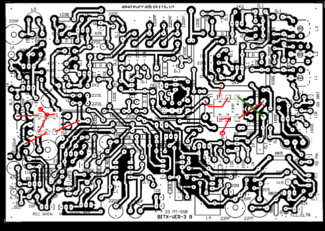
I have an itch to build something when I stumbled upon the BITX20. I previously built a 2W QRP rig and I am pretty much dismayed with its performance. Reading a lot of good things about the BITX (and watching countless hours watching on you tube) and reading K7HKL article and PY2OHH, I had an idea how to convert it to 40M. I ordered a kit from Mr Sunil.
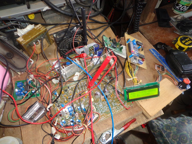
I went to work immediately the moment I received the kit. I did not
follow the instruction manual, i built it starting from the audio amp
and went my way backward to the BPF/RF amp, testing each stage and
making notes as I went along.
The first snag was the RX since I played with the caps on the filter. To solve this, I simply used the original values and adjusted the BFO; measured the center frequency of the filter and programmed the DDS VFO (I did not use the original VFO) and was rewarded with a quiet but sensitive receiver. I am happy!
Completing the linear amp and testing it almost broke me and question my skill to build this radio. I only get 2W and worse it oscillates! I posted at the groups and was rewarded with helpful response from the experts. I also pestered Mr Sunil with countless questions and emails to PE1JXI.
Following WJ6C’s advice, I rewound the output coil making it trifillar then removed the PI filter (at the gate) and 220pF at the drain. This time I got about 4.5W max output.
With nothing else to do, I rewired the DDS to the input of the PA board and set it to have 7.2 MHz output at 250mV. Checked the output and the PA still oscillates! It seems that the PA is easily overdriven, I replaced the mic gain pot with a 10k resistor and 200 ohm trimmer in series.I rewired everything back together again and reviewed everything – parts, connections, voltages, waveforms- all checked out against the manual.
I went away from the project; I am now seriously considering of junking the PA and build another circuit. After several days, I found an 18Vac transformer by accident. I remembered something about the IRF510 behaving better at higher voltages so I quickly connected it and was surprised to have 7W before breaking into oscillation. It will only oscillate if I max out the mic gain adjustment (now it’s a 10k R in series with a 200 ohm trimmer).
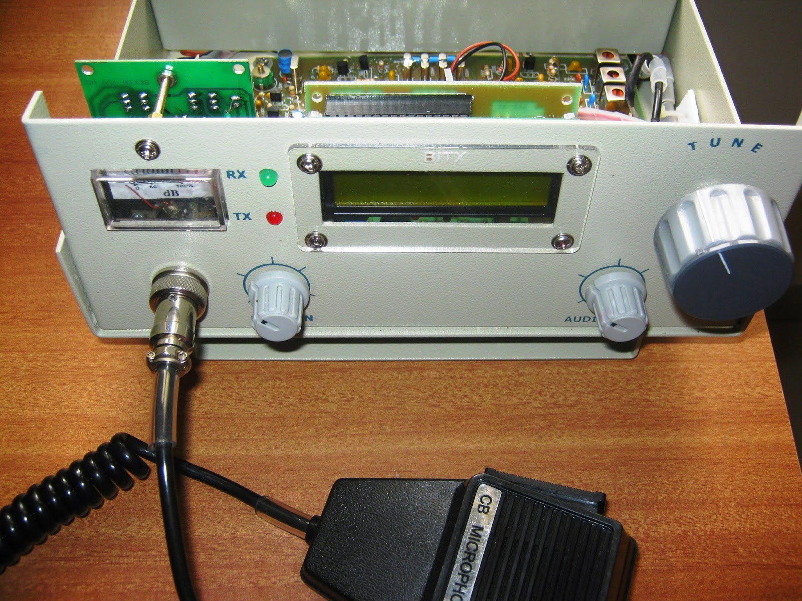
Encouraged, I scavenged another AC transformer, this time it’s a 24V 3amps. Lo and behold I now have 15-20W output with no oscillation on a dummy load(my hopes of making this into a portable radio is now gone)! Excited, I connected it to my 40M antenna via a tuner ( I still don’t have a LPF). I made a successful contact to a station roughly a thousand kilometers away with a respectable 5X5 signal report! I am now a happy BITXer!
However, after a few minutes my BITX40 suddenly went dead. The IRF510 was hot and much to my horror I now have a shorted IRF510! This pulled the power supply down killing my BITX!
Disappointed since the IRF510 is not locally available, I went back to my junk box. I still have a couple of IRFZ44V from –of all junk – a dead UPS, so with nothing else to lose I soldered the IRFZ44V in place of the IRF510.
Much to my delight, I now have close to 25W output on a dummy load even without adjusting anything! I don’t know anything about the IRFZ44N worse my multimeter’s ammeter doesn’t work so I can’t set the idle current properly. Just to be safe, I replaced the heat sink with something bigger; adjusted the gate voltage to 1.75V (it used to be 2.5V); reduced the driver stage gain by adding 1K across the 2.2K R. I now have 12-15w output and slight heating of the heat sink. Having several long QSO with other hams in the Philippines for several hours confirmed that it’s now working.
I honestly do not know if the IRFZ44V is a perfect replacement of the IRF510, I only remember seeing a linear amp circuit on the web which used an IRFZ24 and I asked the author if an IRFZ44V will work. His answer was yes, so I thought this will work for me.
Many thanks to Ashar, WJ6C, PE1JXI, AD5YE, Mr Sunil and everyone for all the support. I really learned a lot and this is what I love most with this hobby, 73!
Jonathan / DV2NAH
*********************************************************************************
We are thankful to Jonathan / DV2NAH for his sharing his experience and story of building Bitx3.
Do you have a similar experience? send in your story so that we can share your experience with the world of Amateur Radio.


.jpg)